
\[ \]
\[ \]
\[ \]
Issue No 69, 12 January 2026
By: Anthony O. Ives
Thrust coefficient [1], inflow [2] and power coefficient [3] were introduced in previous blog articles that I wrote. The previous articles I did just looked at calculating hover and vertical climb performance. Hover and vertical climb performance calculations are usually sufficient for the intial sizing of the helicopter rotor system as they are simple and unlike forward flight performance calculations can easily be done without the need for writing a computer program. Vertical climb performance is usually the operation that requires the most power from the helicopter rotor system, so if it has enought power to climb vertically is should have enought power do most other operations. However, understanding helicopter forward flight performance is important for a number reasons such as how efficient the rotor system is in cruise flight as well as how good the rotor system is at performing limited power operations, etc.
As well as the hover performance articles [1], [2] and [3], I also have a rotor performance calculator which can be used to calculate hover and vertical climb perforance. The rotor performance calculator was previously only available throught downloading an executable file, which understandably some people may be hesitate to do giving all the potential cyber headaches you can get in this modern internet age! So I updated to be like a lot of my other online tools to be available online see the link below:
https://www.eiteog.com/EiteogCALCULATORS/RotorOnline.html
The downable executable file is still available at the link below:
https://www.eiteog.com/EiteogCALCULATORS/Rotor.html
However, I will not be updating the downable executable file in the immediate future but I will be updating the online version to calculate helicopter forward flight performance. If you are using online rotor performance calculator its good idea to review some of the blog posts I did on helicopter hover performance calculations I have already mentioned. The three referenced articles explain the basic method of sizing a helicopter for hover performance and are a really needed prequisite for understanding helcopter forward flight performance. Hover calculations are a simple way of doing the intial sizing of the helicopter rotor system, forward flight calculations are more of an analysis involving iterative process of tweaking the helicopter design so the rotor meets the required performance at other phases of the helicopter flight. Hover and vertical climb performance however are the phases that require the highest hence most demanding power requirements from the helcopter rotor. As the helicopter transitions to forward flight power requirements reduce, see the previous blog I wrote which explains this from a pilot's perspective [4].
In hover the helicopter thrust has only to counteract one force in the vertical direction that being weight. As the helicopter transitions to forward flight another force has to be counteracted in the horizontal direction that being drag. By tilting the main rotor forward that changes the direction of the rotor thrust force. This procedure for transitioning to forward flight from a pilot's perspective is described in an earlier blog article, see reference [4]. Tilting the main rotor forward allows the rotor to counteract two forces rather that just the one in hover. Essentially the rotor thrust has now two vector components one in the vertical and one in the horizontal direction, this is described more generally from mathematical point in another blog article, see reference [5].
The rotor thrust force is not the only property that has two components, the same thing applies to the forward air velocity, it's also split into two components only relevant to main rotor. One component is vertical to the main rotor while the other is horizontal to the main rotor. Vertical advance ratio was introduced in earlier blog articles (see references [1], [2] and [3]) to account for air entering the rotor from the vertical direction. To account for flow entering from the horizontal direction a horizontal advance ratio is defined as follows:
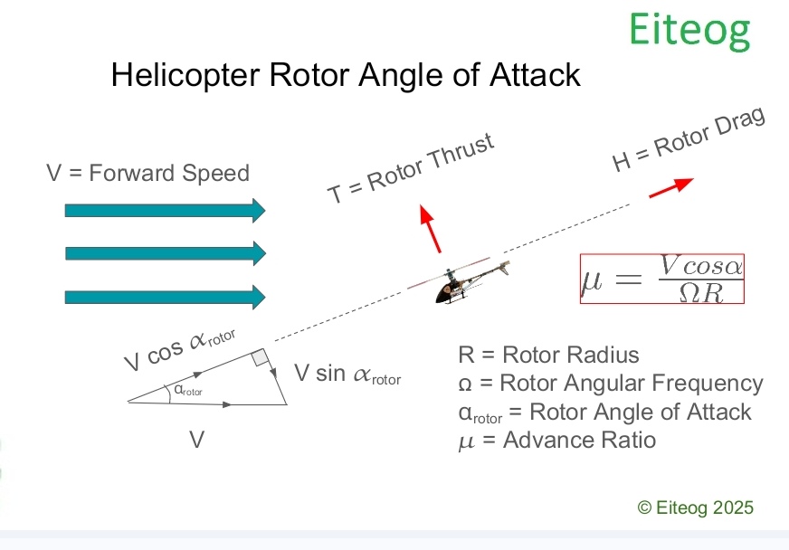
\[\mu=\frac{V cos \alpha_{rotor} }{\Omega R} \]
μ=V cos α / ( Ω R )
V is the helicopter forward flight velocity, αrotor is the rotor angle of attack, Ω is the rotor angular velocity/frequency and R is rotor blade radius. The expression for horizontal advance ratio is slightly more complex to take account of the airflow direction in forward flight hence why the rotor angle of attack needs to be taken into consideration. Rotor angle of attack and other concepts are illustrated in the picture below, the picture assumes the helicopter is in straight and level flight and not climbing however, the same principle should apply for climbing flight as everything is referenced to rotor disk plane.
Thrust coefficient for hover or vertical flight was introduced in a previous blog post [2]. For forward flight the thrust coefficient has to take into consideration some additional parameters such as advance ratio, μ and longitudinal cyclic pitch, θ1s. Advance ratio was introduced earlier, cyclic pitch is an angle of the rotor that varies as the rotor blade spins through each rotation different from collective pitch which is always constant as the blade spins through each rotation. The thrust coefficient for hover/vertical flight only needs to consider collective pitch so hence rotor blade pitch referred for hover is collective pitch. Forward flight however, has to account for both collective and cyclic rotor blade pitch.
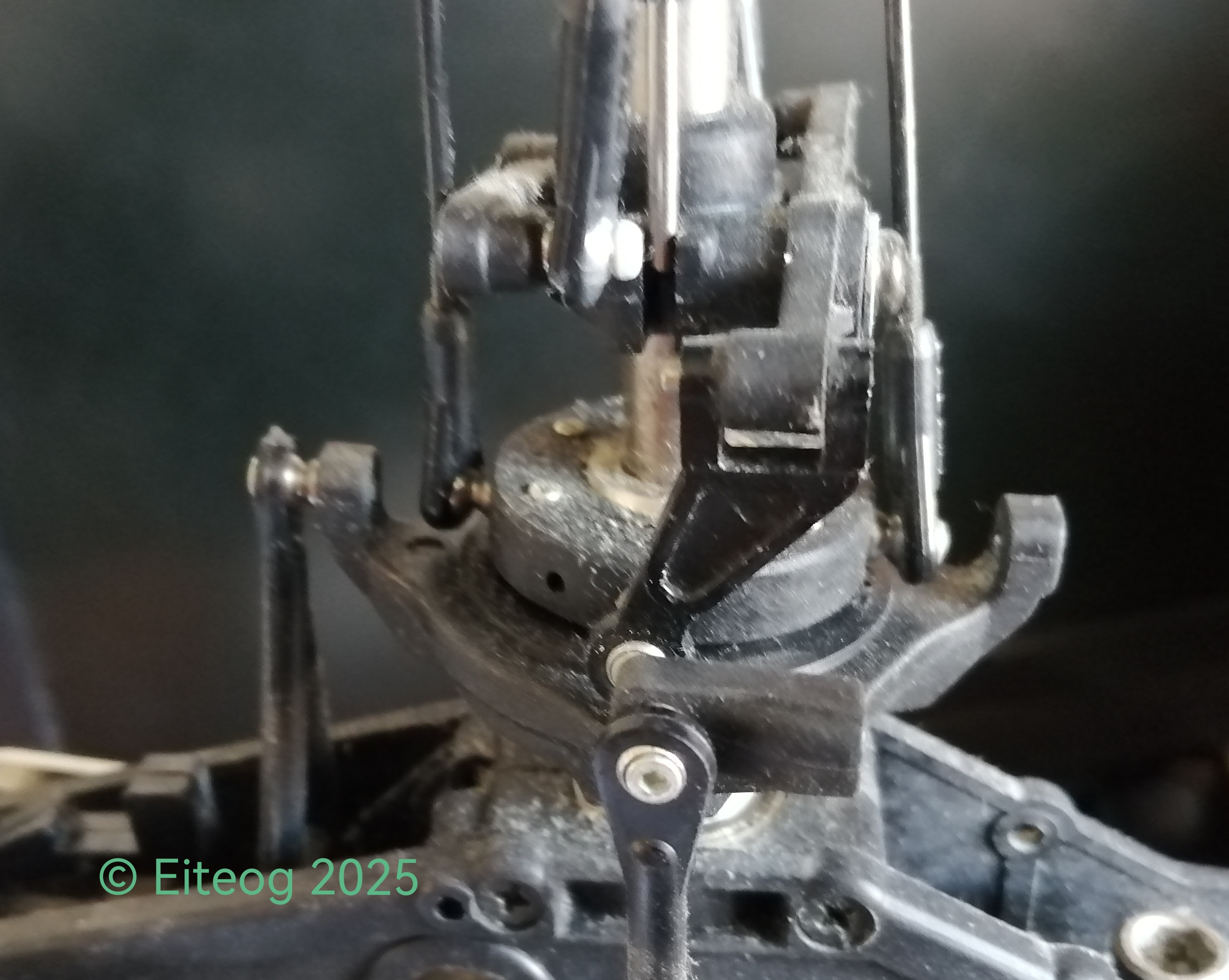
Cyclic pitch is essential to control the helicopter hence to allow the pilot to move it forward, backward, sideways, bank, stop and transition to forward flight. Cyclic pitch is achieved through the use of a swashplate, see picture below, which is a device that transfers the pilot's control inputs into rotor blade pitch angle changes, swashplate and helicopter control is something to be discussed in a separate article but a picture of what a swashplate looks like is given below.
The expression for forward flight thrust coefficient is given below:
\[C_T=\alpha \frac{\sigma a}{6}=\]
\[\frac{\sigma a}{2} \left[ \frac{\theta_{.75}}{3}\left( 1 + \frac{3}{2} \mu^2 \right) - \frac{\theta_{tw}}{8} \mu^2 - \frac{\lambda_{NFP}}{2} \right] \]
Where θ.75 = θ0 + 3/4 θtw, θ.75 is the collective pitch at 75% blade radius position, θ0 is the collective pitch at the blade root, θtw is the amount variation or twist of the blade pitch angle from root to tip. The inflow in the non feather plane is λNFP = λ - μθ1s, λ is actual inflow through the rotor disk. α is the blade angle of attack. Inflow and other parameters can be defined as NFP (Non Feather Plane) and TPP (Tip Path Plane) in forward flight, there are expressions for converting between these and parameters for the rotor disk. NFP and TPP will be discussed in more detail in some later articles.
From the expression for thrust coefficient for helicopter forward flight if the advance ratio is zero then the equation reduces to one for hover as given in previous articles [2]. As was also done previously the expression can also be rearranged to give the collective pitch required θ.75:
\[ \theta_{.75} = \frac{1}{\left( 1 + \frac{3}{2} \mu^2 \right)} \left[ \alpha + \frac{\theta_{tw}}{8} \mu^2 + \frac{3}{2} \lambda_{NFP} \right] \]
If the advance ratio is zero this expression also reduces to the one given previously [2]. The thrust coefficient for forward flight is more complicated to take account of some additional effects that occurs in forward flight such as blade flapping. The expression for inflow is also different which I will introduce next.
Transition region or Translational lift occurs in the forward speed range 25 to 35 knots or advance ratio μ = 0.1 \(\mu=0.1\) can be calculated more accurately when
\[ \lambda = \mu \tan{\alpha_{rotor}} + \frac{C_T}{2 \sqrt{\mu^2 + \lambda^2}} \approx \mu \tan{\alpha_{rotor}} + \frac{C_T}{2 \mu} \]
or
\[ \lambda_i = \frac{C_T}{2 \sqrt{\mu^2 + \lambda^2}} \approx \frac{C_T}{2 \mu} \]
where λ is the total inflow, λi is induced inflow, μ is advance ratio, αrotor is the rotor disk angle of attack, CT is thrust coefficient. Approximate inflow values are based on assuming λ≈0 in the induced inflow term.
For forward flight the ratio of induced inflow to hover inflow is as follows:
\[\lambda = \frac{V \sin{\alpha_{rotor}} + v}{\Omega R}\]
\[\lambda_i = \frac{v}{\Omega R} = \lambda - \mu \tan {\alpha_{rotor}}\]
\[\lambda_i = \frac{v}{\Omega R} \approx \frac{C_T}{2 \mu}\]
\[\lambda_h = \frac{v_h}{\Omega R}\]
\[\frac{v}{v_h} = \frac{\lambda - \mu \tan {\alpha_{rotor}}}{\lambda_h}\]
\[\frac{V}{v_h} = \frac{\mu }{\lambda_h \cos {\alpha_{rotor}}}\]
These values are used to plot inflow curves and determine typical helicopter performance. Now that we can calculate both forward flight thrust coefficent and inflow we can use those to calculate the power required for forward flight using the following equation for power coefficient:
\[ C_P = \frac{kC_T^2}{2\mu} + \frac{\sigma C_{d0}}{8} (1+4.6 \mu^2) + \frac{1}{2} \frac{f}{A} \mu^3 +\lambda_c C_T \]
Where k is the rotor tip loss factor, σ is the rotor solidary ratio, f is the ratio of helicopter parasite drag area to rotor disk area, Cd0 is the airfoil zero lift drag coefficient, A is the rotor disk area and λc is the climbing ratio.
If you plot the power cofficient against advance ratio you should end with a graph like the following:
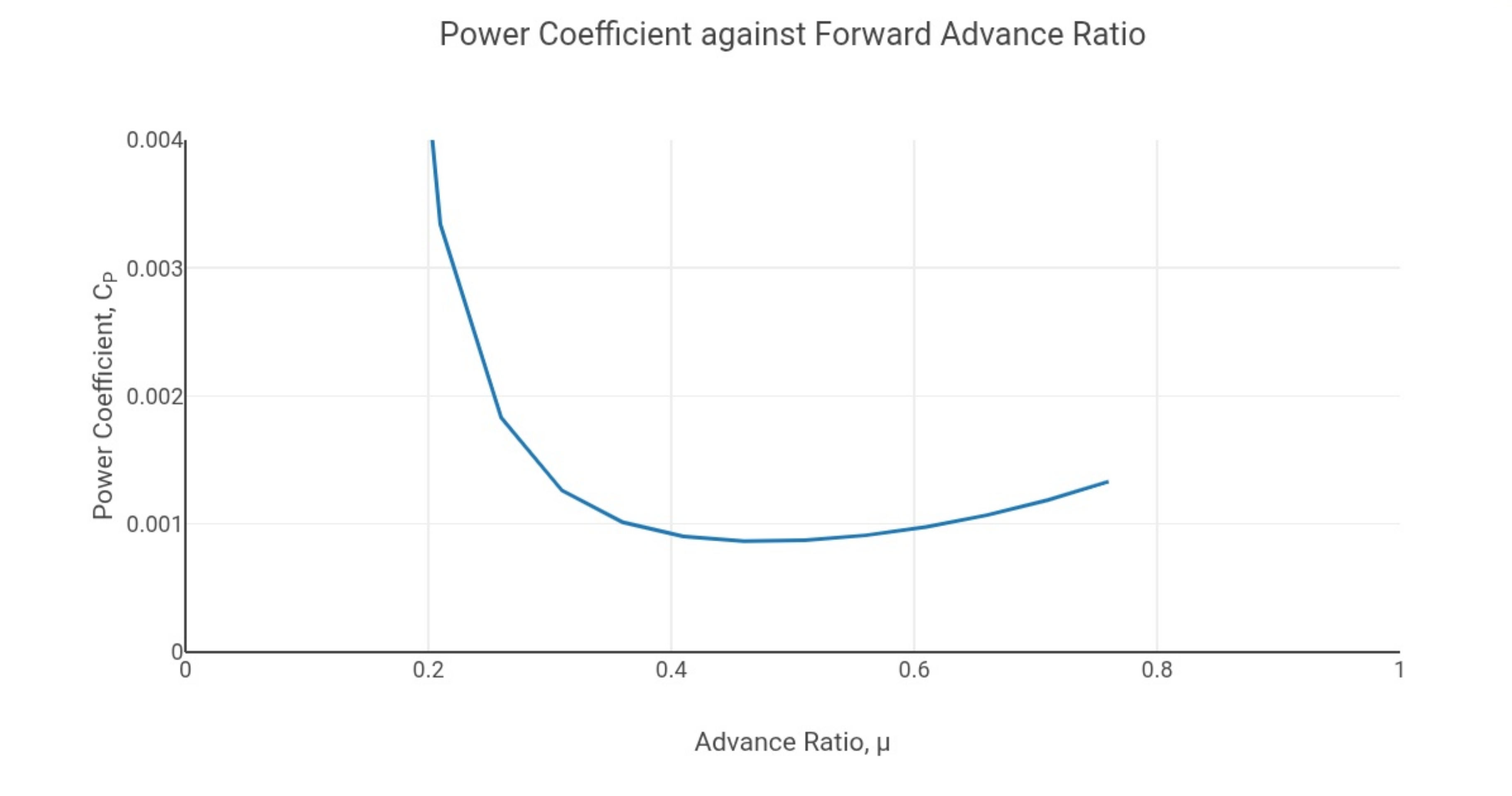
The dip in the graph is at the advance ratio for equivalent transitional lift speed which requires minimum power as described in reference [4]. Therefore helicopters require more power for hover than for forward flight. The graph is also very theoretical as is the equation is implying an infinitive value for hover power coefficient when advance ratio is zero. Hover coefficient is actually a finite value as seen in reference [3]. The graph also implies that power coefficient drops to zero with an increase forward speed and advance ratio, in reality power coefficient increases slightly with forward speed and advance ratio due to parasite drag.
The best practice is to design the helicopter rotor system for hover performance as per references [1], [2] and [3]. Forward flight performance is something to be analysed after you have your helicopter sized for hover just to check trim characteristics, cruise performance, etc. Helicopter optium performance is generally required for the hover.
Please leave a comment on my facebook page or via email and let me know if you found this blog article useful and if you would like to see more on this topic. Most of my blog articles are on:
Mathematics
Helicopters
VTOL UAVs (RC Helicopters)
Sailboat Design and Boatbuilding
If there is one or more of these topics that you are specifically interested in please also let me know in your comments this will help me to write blog articles that are more helpful.
References:
[1] http://www.eiteog.com/EiteogBLOG/No4EiteogBlogThrust.html
[2] http://www.eiteog.com/EiteogBLOG/No11EiteogBlogThrust.html
[3] http://www.eiteog.com/EiteogBLOG/No16EiteogBlogThrust.html
[4] https://www.eiteog.com/EiteogBLOG/No32EiteogBlogForward.html
[5] https://www.eiteog.com/EiteogBLOG/No45EiteogBlogVector.html
[6] Helicopter Theory, Wayne Johnson, 1980, Dover Publications
[7] Rotary Wing Aerodynamics, W. Z. Stepniewski and C. N. Keys, 1979, Dover Publications
![]()


Disclaimer: Eiteog makes every effort to provide information which is as accurate as possible. Eiteog will not be responsible for any liability, loss or risk incurred as a result of the use and application of information on its website or in its products. None of the information on Eiteog's website or in its products supersedes any information contained in documents or procedures issued by relevant aviation authorities, manufacturers, flight schools or the operators of aircraft, UAVs.
For any inquiries contact: [email protected] copyright © Eiteog 2026